Rolling bearings

Rolling bearings have a very long service life in most industrial applications. Since the first attempts were made at the beginning of the 20th century to calculate this life, the methods have been refined further and further and are considered to be very accurate for standard applications. The conditions under which rolling bearings of wind turbines are used differ considerably from this, however: high stochastic loads, continually changing rotational speeds, and interfaces with complex stiffness profiles increase the probability of failure and lead to a situation where failures are not unusual long before the end of the calculated fatigue lifetime. Phenomena which cannot be calculated, such as “white etchin cracks” in the bearings of the gear stages and in the generator often lead to problems, in wind turbines especially.

The certification authority currently does not require a service life calculation for oscillating rolling bearings as are used for the rotor blade bearing; methods used to date cannot be applied reliably. Standstill marks (false brinelling), ring fractures, contact corrosion, core failure, and wear and tear, are therefore typical examples of occuring damage mechanisms.
In 2013, Fraunhofer IWES began conducting research on large rolling bearings of wind turbines to increase their reliability and pioneer new calculation methods and designs. The “Large Bearing Laboratory” (LBL) at the institute’s newly established site in Hamburg bundles these activities together and expands them to include experimental test facilities for bearings of next-generation wind turbines. Experienced bearing experts at the institute have developed their own methods for creating long-term test programs for this purpose. The programs use complex data analysis to generate  he time series necessary for long-term tests which can imitate the different damage mechanisms (contact fatigue, wear, structural fatigue).

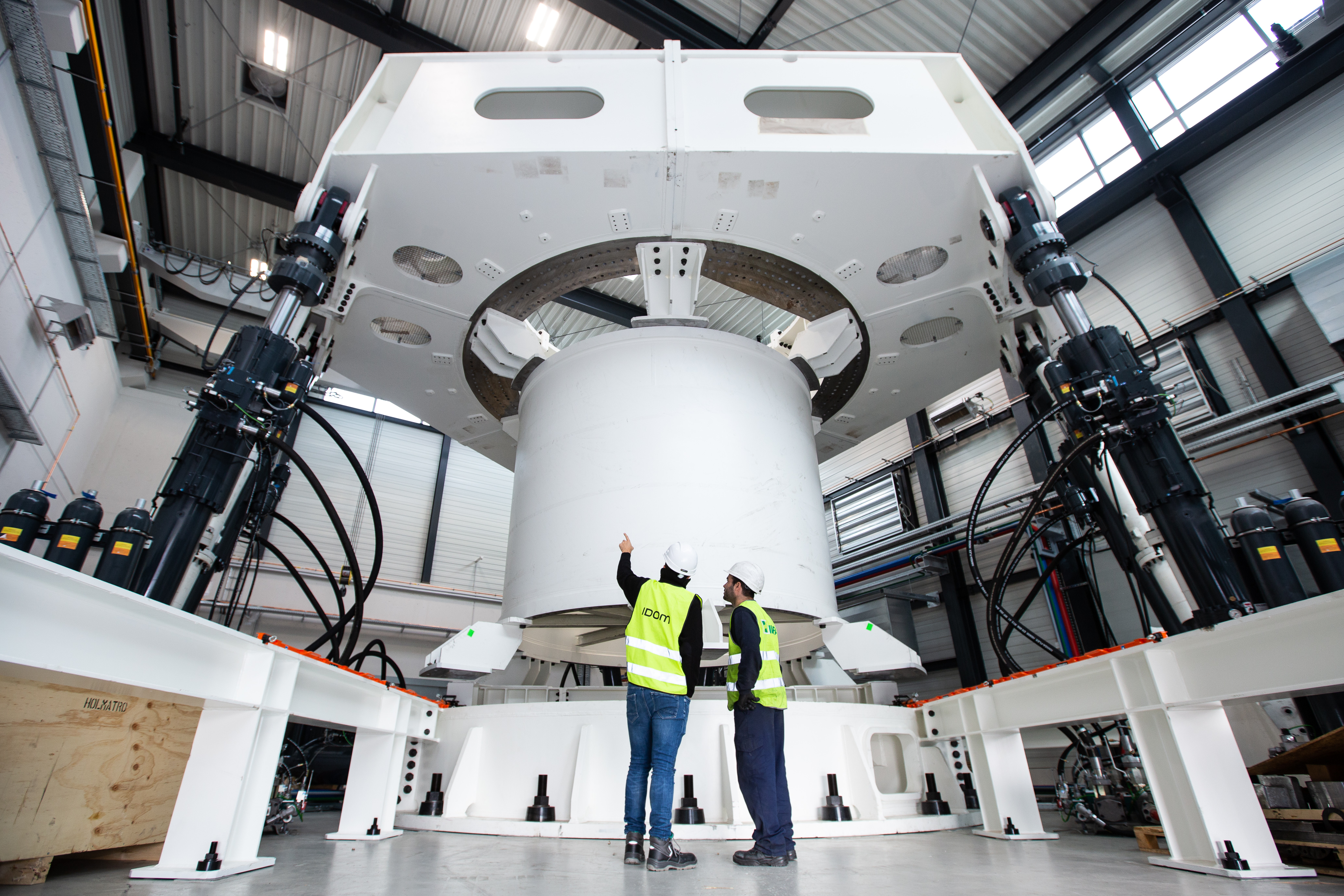
At the large rolling bearing test bench, complex interfaces such as rotor blade and rotor hub close to the rotor blade bearings are emulated by adapter components which reproduce the stiffness behavior of the components so as to be accurate in every detail and thus allow the test specimens to be loaded realistically. The results of the fatigue and wear tests can be used to improve the dimensioning methods and reduce the risk of failure.

© Jan Brandes
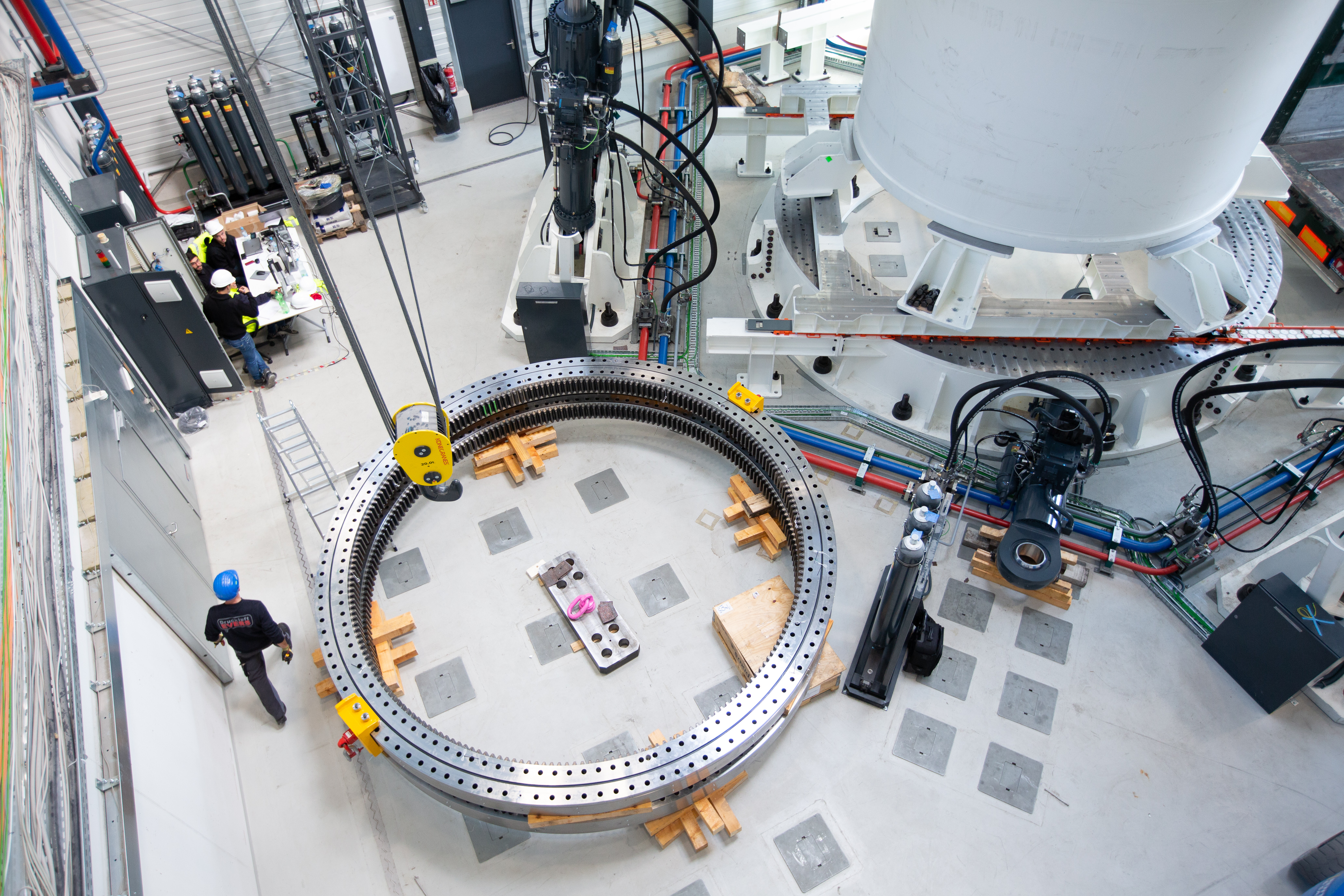
Last approval of the six hydraulic cylinders of the load application.
© Jan Brandes
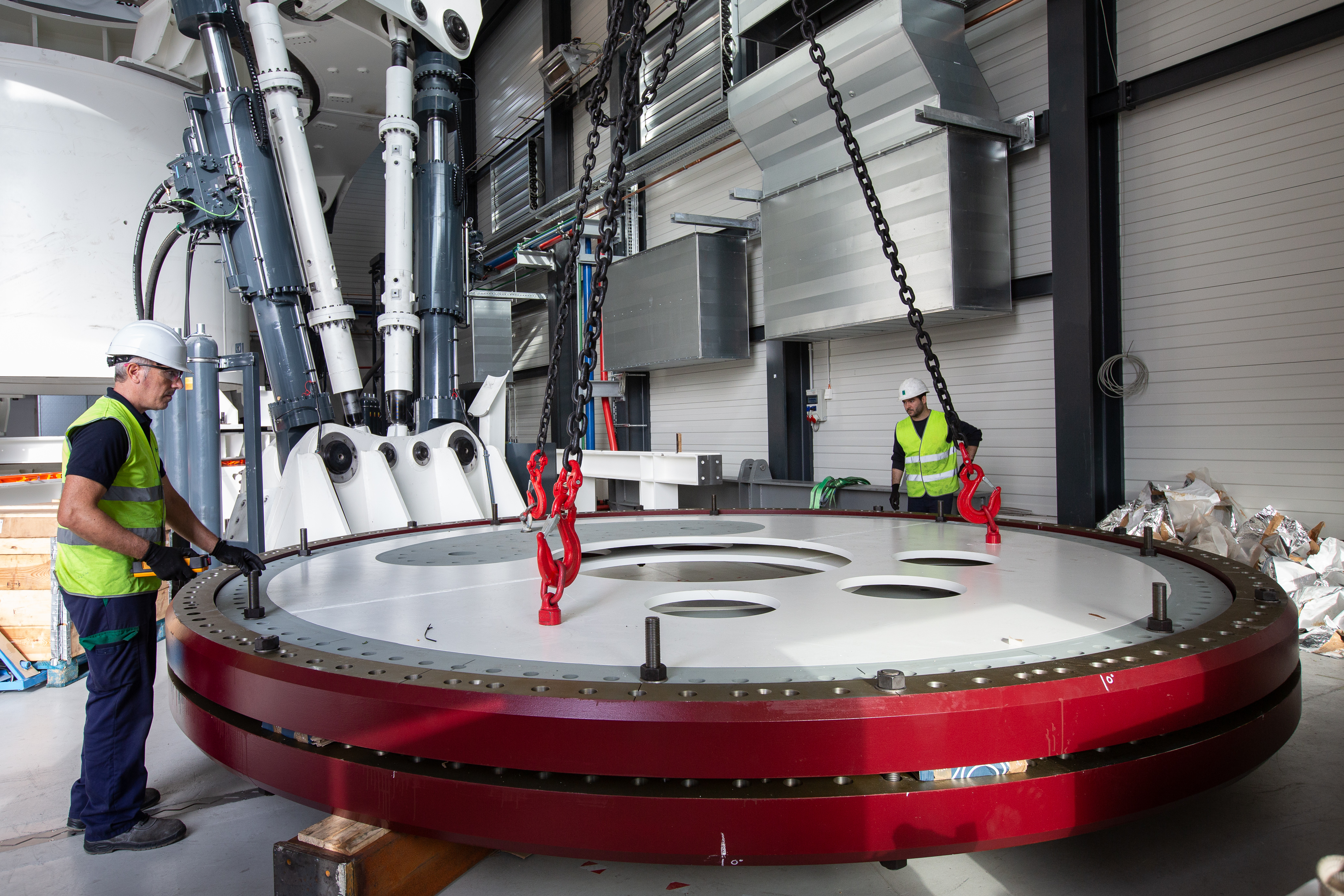
Rolling bearings with a 5m diameter are ready for testing.

The test bench will go into operation in spring 2019. It offers the opportunity to certify a bearing long before it is first used in a wind turbine. Furthermore, it will serve the industry’s interest in shortening test times so that new products can achieve proven commercial viability more quickly. As part of the current collaborative project known as HAPT (Highly Accelerated Pitch Bearing Test), six bearings with a nominal diameter of five meters will initially be analyzed in functional and long-term tests on the bearing test bench.

The simultaneous simulation of the bearings supports the testing work and comprises individual contact simulations as well as global bearing models for FE and MBS analyses. The interfaces (bearing housing, rotor blade, transmission housing, rotor hub, nacelle) are likewise reproduced in FE models. All simulation models are compared and validated with measured data. Individual controllers and aeroelastic turbine models furthermore facilitate the investigation of changes in the operational management, for example with individual pitch control and the associated reciprocal effects on the bearings.

The analysis of simulation and measurement data facilitates the estimation of dominating damage mechanisms and the detailed calculation of fatigue life. It is not only the bearing as a whole which is calculated here, but individual raceway sections, so as to be able to provide precise information. From concept development, simulation, design, and testing through to evaluation, the range of services offered by IWES spans the complete life cycle of a large roller bearing. In addition to the large bearing test bench BEAT6.1, Fraunhofer IWES operates further test infrastructure for rotor blade bearings and main bearings, as well as smaller test benches to carry out basic engineering tests and to test large batches.

Download Factsheet


Technical Data

- Test bearings with diameters of 3 - 6.5 m
- Introduce static loads up to 50 MNm
- Dynamic bending moments of +/- 25 MNm at 0.7 Hz
- Highly integrated control and data acquisition system with very high processing speeds - autonomous operation possible for months
- Measurement system with 500 high-resolution measurement channels and redundant data bases
- Accelerated testing: simulation of loads from 20 years of operation in 6 months
- Emulation of interface parts and their properties

© Martina Buchholz

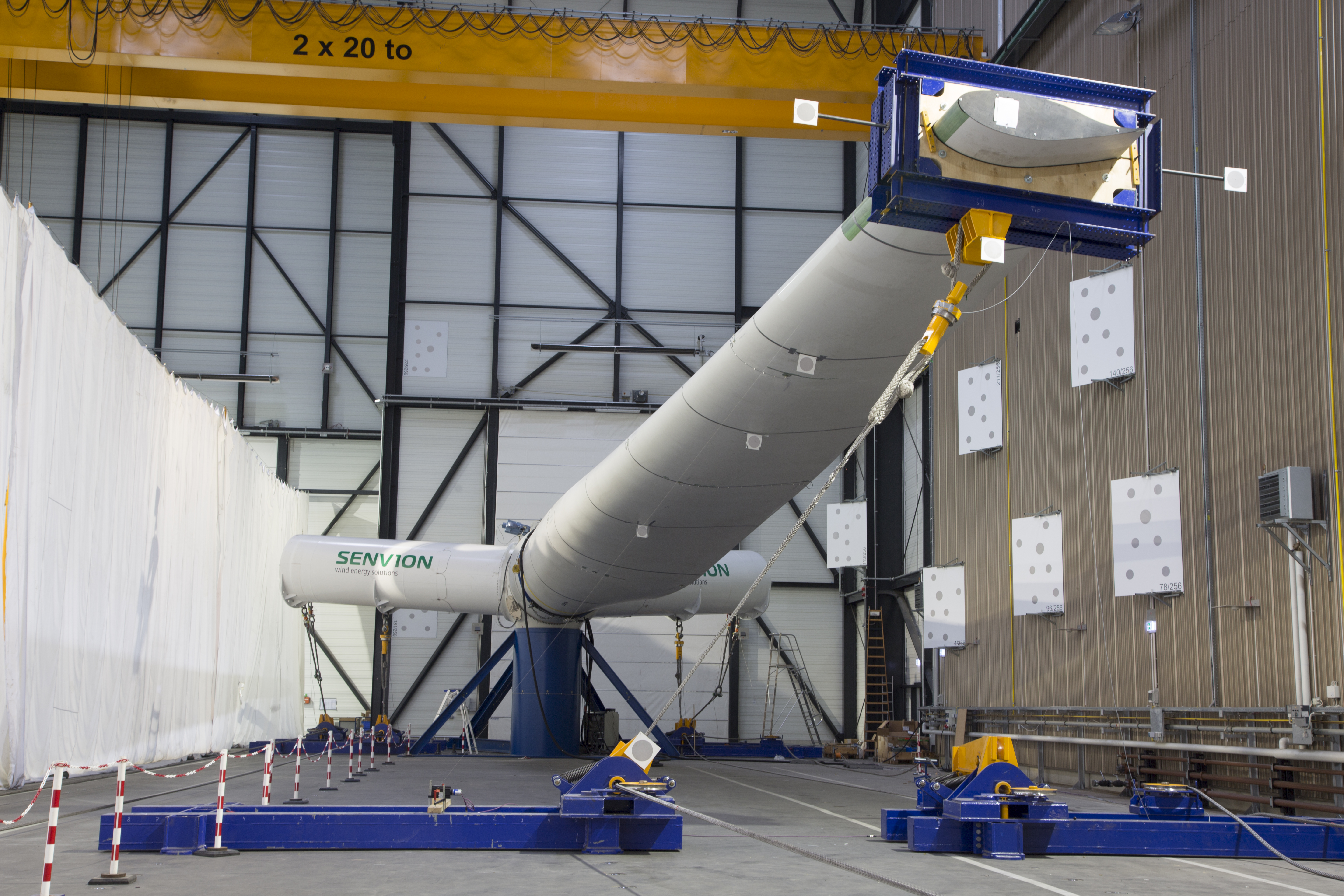
In cooperation with one manufacturer of wind turbines and and one for rolling bearings, IWES has constructed a blade bearing test bench which enables testing of the entire hub/blade bearing/rotor blade group. In this set-up, all the significant interfaces are modelled realistically. A maximum bending moment of 15 MNm can be created on the rotor blade; this moment can be divided into flapwise and edgewise bending Additional load arms on the free blade bearing flanges ensure realistic deformation of the hub flange on the blade bearing. Pitch movements with amplitudes of up to 5° can be realized when subject to loading. The test stand is available for public use: it can be deployed directly to test the hub/blade bearing/rotor blade assemblies; Fraunhofer IWES can also arrange the production of the corresponding components for testing individual bearing

Download Factsheet


Technical Data

- Max. bending moment 15 MNm
- Pitch movement when subject to loading with +/- 5°
- Running of generic programs as well as modified time series
- 400 measurement channels
- Measurement of thickness of lubrication film

The main shaft fatigue test bench for components constructed for 2-5 MW turbines is part of the Dynamic Nacelle Testing Laboratory in Bremerhaven. Acclerated fatigue tests of main shafts have been carried out since 2016. Via hydraulic load application, max. radial forces of 3 MN and bending moments up to 15 MNm can be created. With 300 kW drive power, a maximum torque of 50 kNm for a rotational frequency of 1 Hz is achievable. Thoroughly monitoring via sensor systems shows forces, strain and temperatures and announces the expected growth of the fatigue crack.

Download fact sheet


Technical data

- Max. bending moment: 15 MNm
- Max. radial force: 3 MN
- Max. rotational speed: 60 rpm
- Drive power: 300 kW
- Heavy-duty foundation
- Flexible test arrangements possible

© Hans Kyling

Build-up of a rolling bearing test bench: from conception to operation